Saturday 31 August 2013
Assignment Extension
Just found out we got an extension. I have caught my blog up to about a week ago. It has been a very, very hectic week trying to get everything together for Sunday night and there is a lot of stuff from the last 7 days that still needs to be put up, but I feel I have honoured my pledge and will leave it here for the night.
Component Fabrication Attempt #10
So I'd spent a lot of time printing the floor pieces, but not the things in between. The first attempt was on the Makerbot, it printed fine, however the tabs that I had modeled on the floor planks didn't fit inside the holes in the joining components. This was probably due to the fact that the inaccuracies were compounded as both elements were on the 3D printer. On the replicator any inaccuracies generally increase the size of the component, this is not the same with the laser cutter.
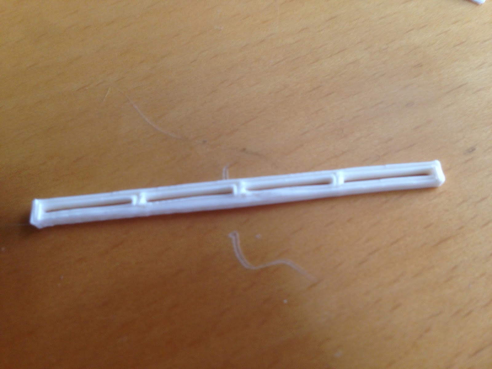
The laser cutter reduces the size of the component. This kind of works well in conjunction with the replicator as the increased size of one fits well with the other. I laser cut four different versions of the rib components with varying internal sizes, however the first one worked the best. Also the thinner the cut, the more the cardboard warped and disintegrated.

VERDICT: SUCCESS
Component Fabrication Attempt #9
So off the back of the last attempt I decided to print fewer components at the same time. I lowered teh layer thickness back to 0.2mm and played around with print speed. I thought that if I slowed down the print speed, especially when travelling between components, I could minimise the errors as well as reducing the snail trails between the components. While I succeeded in reducing the errors, the snail trails were still there. This wasn't an issue though as they were easily removed with a craft knife.


One of the things I was trying to experiment with in this trial was the triangular patterns on the surface. I had spent a lot of time in SketchUp modelling the patterns of the triangles, however I noticed that when printed it was only the larger ones that actually showed on the surface.
VERDICT: SUCCESS
Component Fabrication Attempt #8
I decided to try printing multiple components at the same time to see if it would cut down on print time. These 9 components took nearly an hour and a half, which is almost exactly the same as if I had printed them all individually. The only real issue with this is that it left quite a lot of trails of plastic across the components, which although looked alright, did actually create errors within the components, not just between them. Also, for this print I upped the layer thickness to 0.4mm to see what the effect would be on print time and quality.


I decided not to break apart the components and clean them up as I kind of liked the way they looked like a street lined with skyscrapers. If I learned anything from this experiment is that for the most accurate results, the components should be printed individually.
VERDICT: PARTIAL SUCCESS
Component Fabrication Attempt #7
So after fixing up the bugs in my model I reprinted the mobius strip, but scaled down to 50% of its original size with a 0.4mm layer thickness instead of the 0.2mm. It took about 20min to print, down from 1hr 40min. The issues with the surface were resolved, however because of the thicker layers and smaller size there are a few gaps in the surface which wouldn't be there is printed at higher resolution.


VERDICT: SUCCESS
Component Fabrication Attempt #6
So I decided to revisit trying to print the mobius strip with a single component now that I'd printed a few things on the printer.


There were quite a lot of errors when printing the surface, and once again it was out old friend 'hidden internal surfaces'. I had to go into SketchUp again and remove the many, many, many internal faces that I had left in the model.
This particular piece was printed at 0.2mm layer thickness. It is about 15cm across and took about 1hr 40min to print. I decided not to print it again at full size and resolution after I made the corrections as it would have taken another hour and a half.
There were also quite a lot of additional layers and structures that were built in the model, possibly because of the internal faces, possibly because of reversed faces. Either way they were unlike the usual support structures that Makerware normally adds in and required a lot of work with a craft knife to remove.

VERDICT: FAILURE
Surface Patterns
Based on the fact that the triangular pattern appeared on the surface of my planks when printed I decided to try and experiment with trying to create patterns on the surface by varying the size and direction of the triangles. This required drawing every line one by one to create the triangles of different sizes.


Component Fabrication Attempt #5

Finally a successful print. Having cleaned up the computer model and tweaking the print settings I finally printed one of the mobius planks with not issues. Unfortunately printing upright like I did meant that I didn't get that circuit board pattern on the surface, but the result was far better than printing it flat and so I'd have to make do without the pattern. There is however a different pattern on the surface. There is a repeated triangular pattern that comes from the way that 3D programs create surfaces. It's not as prevalent or aesthetically pleasing as the other pattern, but it is something that I can play with.
VERDICT: SUCCESS
Component Fabrication Attempt #4
With the issues that I was having printing the component laying down, I decided to print it upright. This meant that the only face touching the print bed would be the smallest face. In terms of maintaining accuracy this was pretty much the best option.

The issue that I had was not with the printer this time, but instead with the SketchUp model. I left hidden internal faces in my components. In the image below you can see that when the front face of the component is removed there are more faces on the inside that don't actually need to be there. I deleted the internal faces and then put the front face back on.

VERDICT: FAILURE (But I learned that internal faces cause problems when printing)
Component Fabrication Attempt #3

My next attempt was to print the floor plank as a single component rather than having split it open, this gave the added benefit of reducing the inaccuracy as there was no need to glue two halves together to form the one piece.

The print was a success and had the unexpected side effect of a circuit board type patter on the top surface. This was a result of the way in which I had computer modeled the mobius strip and the way in which the Makerware had sliced the object for printing.

While I really liked the effect, the trouble was that it was only on the top face. The bottom face which was connected to the raft was unclean and a little inaccurate, creating one clean and one unclean face. Since both faces were exposed in the model, this was not quite good enough.
VERDICT: PARTIAL SUCCESS
Component Fabrication Attempt #2

After finally discovering that you cannot print without a raft I finally got a vaguely usable object out of the Makerbot. The butterflied floor planks were printed I carefully extracted them from the raft, however there was an issue.

While it is necessary to print using a raft, it creates the issue of inaccuracy. I had assumed I would be printing on the perfectly flat printer bed, however the raft is not perfectly flat, and when I tried to combine the two halves I discovered that they did not fit together perfectly. The innacuracy was perhaps only 0.5mm, but considering the level of accuracy I needed to ensure the mobius strip shaped actually reconnected with itself, when compounded over 36 components, it was too much.
VERDICT: FAILURE
Modelling Mobius Components

Based on what I learned with my initial printing and some suggestions from Russell and Graham I started modelling my design with fabrication in mind. The idea was to laser cut the rib elements from cardboard, considering they were all identical this would be easy. The floor elements however were all unique and required individual modelling and fabrication.

I took each of the floor elements and butterfly split them down the middle. The idea being that I could glue the two halves together to form a single floor plank. This would mean that the cleanly printed top surface would be the exposed surface.
Component Fabrication Attempt #1
This was my first foray into rapid prototyping on the maker bot and it was a resounding failure.

The twisted globules of plastic may not look like much, but they represent nearly two hours of trial and error printing. The extruded plastic seemed to have trouble adhering to the plate and would be dragged around as the nozzle moved. I tried many different settings with adding supports and rafts and building my own columns, but nothing seemed to work. I then tried printing a simple cube, which worked better, but still had errors. I then tried printing a comb, one of the default objects on the memory card. It worked fine, which meant that the issues were with my model and my settings, not the machine. By this stage it was the end of class and I had precious little to show for my efforts, but I had figure out how to export form sketchup into the Makerware saftware and some basic settings on the Makerbot machine.

The twisted globules of plastic may not look like much, but they represent nearly two hours of trial and error printing. The extruded plastic seemed to have trouble adhering to the plate and would be dragged around as the nozzle moved. I tried many different settings with adding supports and rafts and building my own columns, but nothing seemed to work. I then tried printing a simple cube, which worked better, but still had errors. I then tried printing a comb, one of the default objects on the memory card. It worked fine, which meant that the issues were with my model and my settings, not the machine. By this stage it was the end of class and I had precious little to show for my efforts, but I had figure out how to export form sketchup into the Makerware saftware and some basic settings on the Makerbot machine.
VERDICT: FAILURE
The Exam
Having already spent a number of hours modelling in SketchUp, I had a fairly clear idea as to what I was planning on making for the exam. After getting the all clear from Russell to defy the laws of physics I started to make the mobius model. It is a fairly simple process of creating the one component 36 times in a radial circle and then rotating each on them 5 degrees. This means that by the time it has completed the circle there is a 180 degree rotations. It is also important to ensure that the component has 180 rotational symmetry, otherwise it won't match up after it has completed its journey around the circle. My idea was to 3D print the ribs of the circle and then laser cut the infill panels for the floors and walls. Russell however told me that it would be better to do it the other way around and laser cut the ribs, then 3D print the floor, knowing what I know now, that was the best piece of advice I could have been given.


We had the option during the exam to go listen to Graham as he explained how the maker bots worked. I felt as though my design was sufficiently developed and that it would be worth while. Russell then encouraged me to try and print my initial mobius strip as I already had a 3D object. I spent a little while tidying up the model, and then went off to try and print it.
Concept Development

Also, here is the first completed mobius object I made in sketchup. Unlike my other attempts it is not just a surface, but is a solid object with completed faces.

Agyness Deyn - Mobius House
There were a number of things that I was thinking about with the concept for the first house. In class Russell talked about a how the first house did not have a site, and he envisaged something which you could pick up and turn around and not really know which way was up. This led me to thinking that because it existed without a site, it did not necessarily have to obey conventional laws of physics. I was almost immediately put in mind of a Mobius strip, a conceptual object that is difficult to define as its inside face is the same as its outside face. It is thin, nebulous and abstract, qualities of both the mobius strip and Agyness Deyn.


I did some initial test models in SketchUp to try and figure out the best ways of modelling a mobius strip and to iron out any issues I might come across before the 6 hour exam.


I did some initial test models in SketchUp to try and figure out the best ways of modelling a mobius strip and to iron out any issues I might come across before the 6 hour exam.


Blue Foam Modelling - Part Two
The first thing that I learned about slicer was that it doesn't really like small objects. It was much easier to slice an object at 1:1, and then scale the slices down to 1:100 afterwards, rather than scaling the object first.
The next issue with exporting from SketchUp is that it doesn't join any of the lines that it creates. It was worth going into Illustrator and joining all the lines as it reduced an 'estimated' laser cut time from 48 minutes to 14 minutes.
I am not totally familiar with Illustrator and selecting and joining all the elements was a little time consuming, but worth it in the end. It also gave me an opportunity to reposition all the numbers. It should also be noted that I added a cylinder through the middle of my model that I could use to position the elements when building the object after cutting.


I was initially intending to use wire or dowel through the middle, but they didn't work very well. Luckily a toothpick was exactly the right size.


The finished and assembled object, and it's comparison with the original foam model.

If I were to do this again I would use two integral guides to ensure that there was no twisting of the flat elements during assembly.
Blue Foam Modelling - Part One

The first thing that I did was photograph the foam from all different angles so I could generate some curves for curviloft to use.


Unfortunately curviloft did not enjoy the curves that I fed into it.

I then used two curves and intersected the forms, then added in some details manually.

Whilst not perfect it was similar enough to my blue foam object and good enough to feed into slicer to generate something that could be laser cut.
Tune in a 1pm for the cutting and assembly of the box-board laser cut object.
My Pledge
So, I have fallen quite behind with my blogging. Blogging, keeping a journal or keeping a visual diary is not something that I do naturally and although I generally have all the scraps of paper laying around in my room somewhere, I very rarely go to the effort of combining them all together into a coherent document that details the steps that I went through. I'd like to think that the finished product speaks for itself, however this often isn't the case, and so I really should make an effort to do these diaries more thoroughly.
Anyway, as I sit in my room and glue together the 144 components of my Mobius House and then attempt to build the pool element I thought I would catch up on my blog by putting up a new post every hour until I have caught up. This is my pledge.
The next post should be up a little after 12noon and will cover the first task of 3D modelling a blue foam element and then slicing and laser cutting that model. I will see you then.
Subscribe to:
Posts (Atom)